
FenestraPro leverages the Revit Energy Model to gather information on spaces and surfaces. If the energy model only partially generates or is not successful, there will be missing or no data available to proceed. It is therefore important that the energy model in Revit generates successfully and is as complete as possible. FenestraPro will also show if all spaces/surfaces were created.
Typical reasons that elements are not being read can be; elements are not room bounding, element functions are incorrectly set (exterior/interior walls), floors used as roof elements, gaps in the enclosure, room separation lines on plan interfering with identification of elements, generic/imported geometry (non-Revit elements), openings created on surfaces then glazing inserted, sandwich construction (walls/ceilings/floors) modeled in adjacent layers, elements hidden/on different Phases/in linked files or Revit settings preventing correct analysis. These are explained in more detail below.
The EAM Check tool in FenestraPro can be used to diagnose issues and assist in improving the energy model if required.
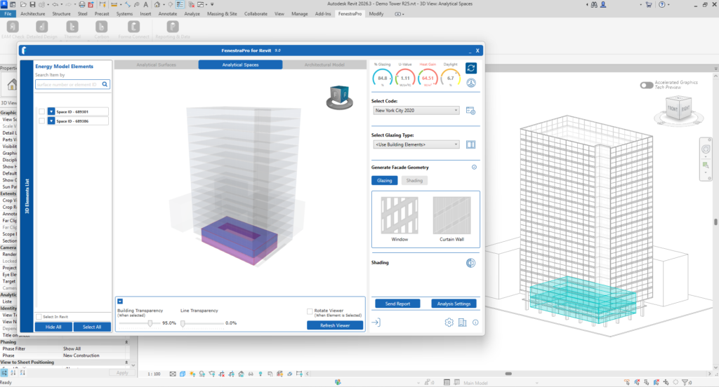
In the image below, only some energy spaces were generated in the model and others are missing. This may be due to various reasons which are described below.
Revit Settings that should be correct before analyzing your project: (these may not affect the energy model but are required to get correct results in FenestraPro)
- Ensure that the Site Location is set correctly in Revit (this will affect Climate data and Solar Loads). This may be set in the Manage Tab in Revit.
- Ensure that True North orientation is set correctly for the project on site. This will affect orientations and results.
- A Project Name should be defined as a minimum under Project Information in Revit.
- It is also useful to check periodically if Autodesk Revit is kept up to date with any latest update. You may check this under ‘Autodesk Access’ (previously the Autodesk Desktop App)
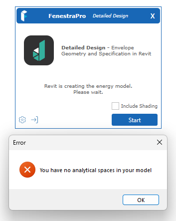
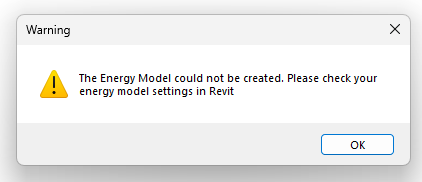
It may happen that the Revit Energy Model cannot be created. In this case a message will display when you try to launch FenestraPro. If you are getting some energy spaces, you can try launching the EAM Check tool which will help diagnose issues. If no energy Model is created in Revit, FenestraPro will not launch.
You may use the guidance on this page and in the Model Preparation section to diagnose issues. You may also contact us : support@fenestrapro.com for advice if needed.
Quick Check List
Guidelines when the Energy Analytical Model (EAM) in Revit does not generate at all or is incomplete:
- Have you checked the Energy Settings?
- Energy Mode – set to ‘Use Conceptual Mass and Building Elements’
- Ground Plane – this is the level that you wish to start analysis (there should be geometry on this level). The Ground Floor of the building should also be on the same level as the Ground Plane setting under Revit’s Energy Settings. All levels below this will not get analytical surfaces (they may however still get analytical spaces).
- Project Phase – this should contain the geometry that you wish to analyze and match what is displayed in the Revit View.
- Analytical Resolutions – these will affect the configuration of analytical surfaces and spaces on the model. It may be worth adjusting resolutions if some areas of the energy model are missing and this does not seem to be due to other factors (see below).
- Perimeter Zone Depth – this setting controls how deep that internal spaces are from the building envelope. If the actual room or space is less than this value, the actual room depth is used instead.
- Is the setting to only ‘Use Elements Visible in the Current View‘ checked? In this case, only limited geometry in the model will be analyzed. You may wish to uncheck this or review view settings in Revit.
- Is the setting under ‘Area and Volume Computations’- ‘Areas and Volumes‘ checked? This setting should be used rather than ‘Areas Only’.
2. If the Energy Model is incomplete/fails
- Check your model for gaps or where elements do not join fully (where walls join roofs and floors). Close these gaps/openings. Where you have garage door openings into an underground car lot, place a roll-up door etc. It may also be useful to look under the building at ground floors, and roof soffits etc.
- Check underneath the model for Floors – do all areas have floors to enclose the spaces? Have you enclosed overhanging roofs with soffits?
- Check Element Functions – Ground Floors should be strictly ‘Exterior’ function and Internal Floors should be ‘Interior’ function. Create new family types if required to separate interior and exterior elements. Where elements start inside a building and continue outside, have a break and use an ‘Exterior’ function type element (eg. balcony floor, where an internal floor becomes an external roof etc). Avoid using ceilings as roofs or externally etc.
- Are elements set to ‘Room Bounding‘? Typically walls, floors and roofs should have this setting checked, unless there is a reason to ignore them.
- Are some Roofs modeled as Floor elements? Roofs should be modeled as roof elements so that the EAM can identify where spaces terminate. Modelling floors as ceilings and then adding roof elements above this can also complicate the energy analysis.
- Are Wall Openings used to define the extent/dimensions for glazing elements and glazing then inserted into this opening? This can interfere with the energy analysis. Remove such openings in walls.
- Are Room Separation lines used around the perimeter of the internal spaces? These can also interfere with energy analysis and should be removed.
- Are walls modeled as adjacent layers in Revit? (sandwich style construction) rather than using the Structure – Edit Assembly method under Type Properties. Avoid modeling walls side by side to build up a thickness. Use ‘Type Properties’ in Revit for the element to define the various layers, thicknesses and materials.
- Are Generic Elements or Imported Geometry used in the model? These will not generate analytical surfaces or spaces in Revit and therefore no energy model will be created. Remodel generic geometry if required as Revit elements.
- If Linked Files are referenced in the project, check that these are also set to ‘Room Bounding’. This will help to complete the enclosure. The Facade should not be modeled as a link since access will be required to adjust type properties for the elements. Roofs, Internal and External Walls and Floors may be imported as linked files. Walls ih glazin should be modeled in the host project (not as a link).
- Check View Settings to review if any other hidden geometry or massing exists in the model.
Element properties will not affect the creation of the Energy Model in Revit but will affect the values that are displayed for Analytical Surfaces (whether there are detailed or schematic properties present or if no properties are assigned). If you change parameters in Revit’s Energy Settings, you will need to close these Revit windows first before you use Refresh in the application as it will nt be able to update when these remain open.
It is also worth checking ‘Warnings‘ in Revit under the Manage tab – ‘Inquiry’ panel. This will provide a list of suspected issues. Not all issues listed here are critical for the Energy Analytical Model. Typical Issues listed might be duplicated or overlapping elements, elements off axis, invalid elements that could not be upgraded from a older Revit version etc. Element ID’s may also be provided which can be searched in Revit and the problem area isolated for review.
Since FenestraPro for Revit v8.0 (for Revit 2025), the EAM Check tool can help you diagnose and fix some of these issues.

Possible Issues:
For the Energy Model in Revit to generate correctly:
1. The correct Energy Mode (‘Use Conceptual Masses and Building Elements‘) should be used in Revit.
For recent Revit versions, the ‘Use Conceptual Masses and Building Elements‘ mode is correct for all model types (instead of ‘Building Elements’ or ‘Rooms and Spaces’).

2. Element Functions should be correct (do not use ‘Exterior’ Walls internally or use ‘Interior’ Walls externally (this applies to both solid and curtain walls). This may create confusion in the Energy Model but Revit will attempt to intelligently use elements, space conditions and adjacent rooms to identify inside and outside areas. It is good practice in any case to use correct functions depending on the location of the element as this will cause an issue later when using FenestraPro to identify energy surfaces.
Where elements begin inside the building and extend outside e.g. interior floors extend to balconies, or exterior walls extend inside the building, there should be a break at the envelope face and separate elements modeled with appropriate functions. To review an element function, select the element in Revit and use Edit Type to open the settings. There is a setting for Function with a dropdown list. This can be done for solid walls and curtain walls as well as floors. Note: Roofs do not have this setting as all Roofs are typically ‘exterior’.


3. Check the Perimeter Zone Depth is appropriate for your project. This is the distance from the building facade defining typical room depths. It is within this area that Heat Gains and Daylight results are considered. This can typically be set to 15-20 feet / 6 meters as a guide. If the actual room or space is less than this value (defined in the model by internal walls etc), the actual physical distance in the model is used instead. A low value for the Perimeter Zone will produce higher value results as the Heat Gain is more concentrated. A larger value for the perimeter zone will produce lower results as the Heat Gain is more dispersed. If this value is too low, it might create divisions in the energy surfaces which will affect the extent and number of surfaces later in the application.


The Extent of Surfaces may not be as expected in the application, depending on the Perimeter Zone Depth setting in Revit (Analyze – Energy Settings) and if the Perimeter Zone Division has been checked (turned on). You may simply uncheck the Perimeter Zone Division setting to resolve this issue or alternatively, adjust the Perimeter Zone Depth value.
4. Check that the Phase set in the Energy Settings matches that set for the elements that you wish to be analyzed. Typically this is the same as that set in the active 3D View used for analysis.
5. Check that the Ground Plane is correct for your project. This is the Level in the model where you wish to start analysis (levels below this will be ignored). Levels should also be set correctly in Revit to line up with Floors and Roofs etc. You may wish to ignore some levels such as parking, basements etc. It is not possible to skip levels. If you have set the Ground Plane above the actual floor level in the model, you may get a warning in the application about not having any Ground Floor in the model. This can be resolved by adjusting this setting in Revit (the Ground Floor of the model should use the same level as this setting in Revit). Note: Energy Spaces may still get created in Revit for lower levels, if you set the Ground Plane to a higher level, consequently these will then display in FenestraPro also but selecting them will not produce results for these areas (results for the entire model will continue to display).
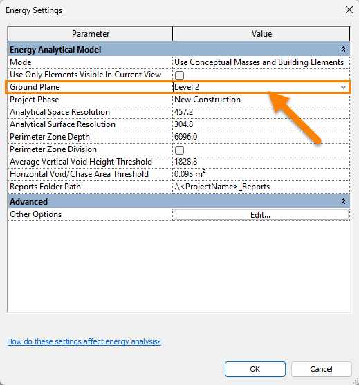
Since Revit 2024, you may also define a range of levels using whatever is in the current Revit View (scope boxes, section boxes etc to define specific levels for analysis). Energy Surfaces/Spaces in Revit will then only be created for these selections. FenestraPro will also only display these defined areas, so this is a way to isolate areas of your project for analysis.
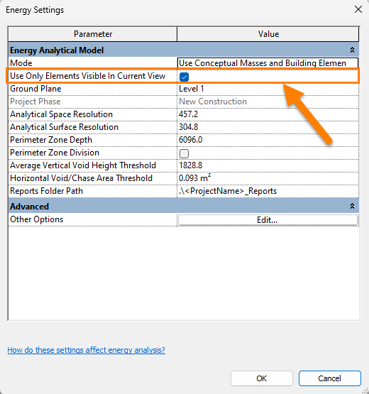
6. Check that Analytical Resolutions set in the Energy Settings are correct (Revit default values may have been previously modified to cause an issue). FenestraPro allows easy access to the resolution settings in the EAM Check tool. Adjusting here in the application will also update the Revit setting. You can also find these under the Energy Settings in Revit (Analyze tab – Energy Optimization section – Energy Settings).
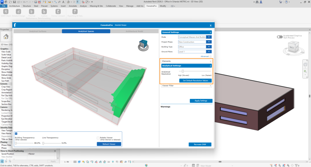

These values will define the tolerance of gaps between elements in the model. If these are set to a lower value, this will increase the time generating the Energy Model. The values set should also be less than the width any surface you wish to include eg. if the value set is 6’-0” (1.8m) (width of a surface) but there are surfaces of only 3’-0” (0.9m) in the model, these surfaces will be ignored. Units displayed relate to the Revit project. Guidelines on typical values as well as maximum and minimum values from Autodesk can be found here
If some Surfaces are not displaying in the Energy Model or are badly fragmented, you may wish to adjust this value. Resolution settings will affect the extent of Energy Surfaces created. Other factors such as abutting or clashing elements or embedded structural elements can also interfere with the Energy Surface. For example, internal walls extended through an external wall core may interfere with how the model is read for energy analysis (identifying energy spaces and surfaces).
The area of the Surface is also dependent on resolutions and model conditions. FenestraPro uses these Energy Surfaces to calculate results, so if they are very fragmented, you may need to experiment with adjusting resolutions or modifying the way elements are joined.
7. Recommended – It is a good idea to create the Energy Model in Revit (Analyze tab) if the project has not been analyzed before and you wish to check for any warnings or you suspect that there may be modeling issues. Any issues that require attention may then be resolved before launching FenestraPro. Warnings may be viewed in the Manage tab of Revit. The application will also provide guidance when only a partial Energy Model creates or were there are modeling issues. You may also launch the application and it provide guidance on model issues.
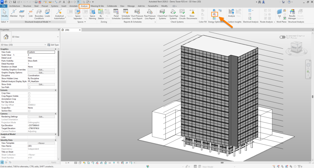
8. The Room Bounding setting in Revit should typically be used for envelope elements. Linked files should also be set to this if they have elements which enclose the building (Roofs, Floors, Walls etc) otherwise the Energy Model may not generate or only partially create. Glazing Elements should be in the host project (as the application needs access to review and change analytical properties).

9. Major gaps in the building enclosure must be resolved to generate a successful Energy Model. Small gaps may be tolerated. Check where walls meet Roofs and Floors. Also check under soffits and Ground Floors where the building may have gaps to the exterior.

If you suspect gaps in the model, go to a Plan View in Revit and try to place Rooms or Areas. If these cannot be placed, this will indicate issues with the enclosure where room bounding elements cannot be identified (possibly non-Room Bounding elements, gaps where elements join, generic geometry etc).

10. Model element types should be used correctly where required. For example, Roofs should be modeled as Roof elements (not Floors), Roof Soffits should not be modeled as internal ceilings to enclose gaps etc. Revit will use element types and functions to identify interior and exterior spaces so it helps if these are correctly modeled.

11. Wall Openings should not be used to create voids in walls and then glazing elements inserted into this void. This tends to interfere with the Energy Model. It is recommended to insert glazing elements directly onto the model. You may use reference lines to outline the extent of openings if required. Openings can be used to create voids in solid walls if needed but not where glazing is to be inserted.

12. Room Separation Lines placed around the perimeter of a model will interfere with the Energy Model and should not be used here. You may use these to define internal rooms or separate areas where no physical elements exist but avoid using these around the perimeter (inside the envelope). Revit will look for the physical elements (walls) to identify where spaces terminate and these lines introduce a barrier that will prevent envelope elements being read. When placing these lines on plan, a message may display in Revit to warn that the ability to find Room Boundaries may be compromised.

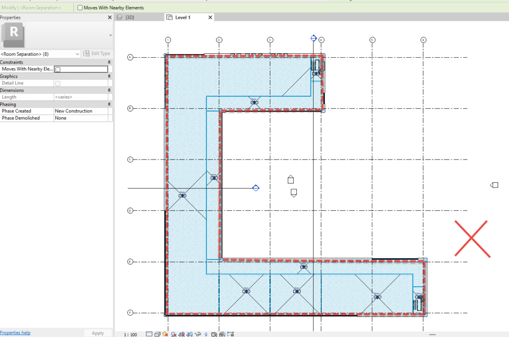
13. Modeling layers of walls, roofs or floors by placing several separate elements side by side or on top of each other (sandwich type modeling) should be avoided. This is sometimes done instead of using the correct structural assembly method to define layers and materials for a single element. Separate element types placed adjacent to or on top of each other will not produce energy spaces or surfaces. This relates to modeling Walls and Roofs and Floors. Several separate elements should not be ‘layered’ beside or on top of each other (use the Structure feature in Revit’s Type Properties – Structure – Edit to define assemblies.


14. Generic Elements (non-Revit geometry) used in a model will not be read correctly to generate Energy Spaces or Surfaces. This may be geometry imported from other formats (such as DWG files, Rhino, Sketchup, Blender etc or saved as different file types). Sometimes, a complex enclosure may be modeled in another software and imported into the Revit project. Typically, this will not generate an Energy Model in Revit as it will not be recognized as a BIM object and only have meshes or polysurfaces. This geometry may need to be remodeled as Revit elements. FenestraPro will help you to identify generic elements under the Building Elements tab or you may find a category in Revit that lists these elements (under the Project Browser – Families – Generic Models).

15. The ‘Areas and Volumes‘ setting should be set in Revit under Room & Area – Areas and Volumes computations. This does not appear to be an issue in recent Revit versions and the energy model should generate regardless. You still may need this setting to produce data for Room Schedules. There is more information from Autodesk here


Although the application will support fully advanced detailed models, a lean model may perform better. Calculations will be faster if the model is reduced to the basic envelope and internal walls. You may detach or save a copy of a model to simplify/purge the file without affecting a shared project. It will also be easier to troubleshoot where issues are without extraneous annotations, Scope Boxes, Views, Sheets etc
Optionally, elements that are not required for analysis may be removed if it is convenient eg. Topography, entourage, mechanical equipment, structure, plumbing, furniture, unused families, drafting views/details, additional sheets, schedules etc.
16. If you are getting analytical spaces and surfaces where there are no enclosed spaces (e.g. where there is a missing storey or recessed area), check the model for the presence of a conceptual mass. When using the energy mode ‘Use Conceptual Masses and Building Elements‘, any mass present in the model will receive analytical spaces as well as detailed elements (walls, floors and roofs), so these masses might need to be removed.
17. If Analytical Surfaces are missing, you may have geometry which touches the exterior envelope and interferes with the creation of Surfaces. Elements such as exterior balconies may need to their settings adjusted in Revit so that they are non-Room Bounding (Floor/Walls/Screens etc).
Limited Energy Model
FenestraPro can use a limited Revit View to isolate areas of the Energy Model (even if the full energy model is created in Revit). By using a scope box or section box in Revit to frame a view and then launching FenestraPro, the application will focus on a specific area of the model (even if a full Energy Model is created in Revit). The FenestraPro Viewer will include the full extent of surrounding elements which enclose the defined space (walls, roof, floors) since these cannot be trimmed. The Energy Space(s) displayed in FenestraPro will however be limited to the areas defined in the 3D Revit View. The full extent of any selected room(s) or space(s) to be analyzed must be visible in the Revit View that you define and must not be cropped or trimmed. The scope box or section box does not have to fit exactly and can extend beyond the space(s). All spaces whose full extent lies within the defined view will be included in the analysis.
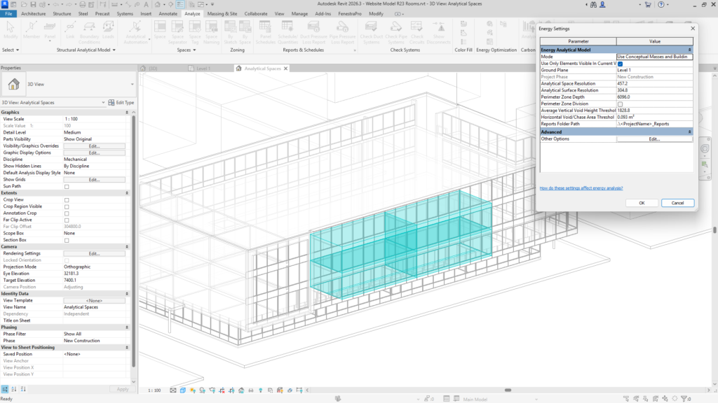
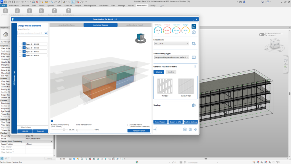
Since the release of Autodesk Revit 2024, you may define an area of the model to focus analytical surfaces and spaces. This is faster than creating an Energy Model for the entire project and allows you to isolate specific areas for review. This is achieved by defining the Revit View using a scope box or section box etc and then using the setting in Revit’s Energy Settings to limit the Energy Model only to elements within this view.
Note: FenestraPro does not strictly require this Revit setting to focus on an area of the model, as long as this is defined using a scope box or section box etc.
By simply defining a limited view in Revit, an Energy Model for the entire project will still be created unless the Revit setting shown below is used. After the limited Energy Model has been created, you may toggle the scope box or section box on or off (e.g. in the Analytical Spaces View) to see the area in context. This will not affect the energy model which has already been created. Perimeter Zones
Perimeter Zones are defined from Revit’s Energy Model. The depth (from the external envelope) within which results are considered, can be set in Revit’s Energy Settings. You may also group the model into spaces in FenestraPro and view relevant Surfaces associated with that Space.
- For open plan spaces, all Surfaces that feed into a space will need to be included in the results (when analyzing the space).
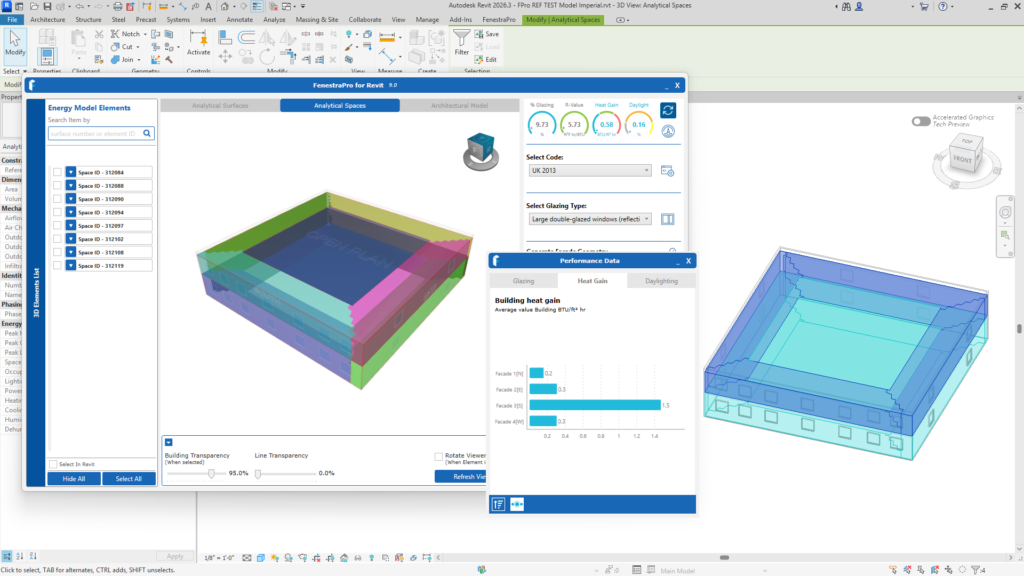
- When the plan is divided by internal walls, perimeter zones take on different extents. Only relevant Surfaces are included in the results.
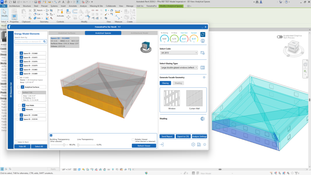
- When the design allows for recessed areas etc, this along with the Energy Settings in Revit (analytical resolutions, perimeter zone depth, perimeter zone division on/off) may produce divisions on the energy surfaces which are unexpected. It is a good idea to review the Energy Model in Revit to ensure that analytical spaces are sorted and divided as expected before proceeding to analysis.
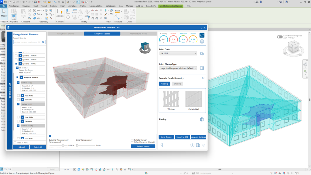
If more divisions are defined in the model, this will typically take more time to analyze.
If you are interested in studying the effect of different glazing types on the Heat Gain and Daylight in a space, dividing the model into separate zones is helpful (rather than open plan conditions). Also review the Perimeter Zone Depth value in Revit’s Energy Settings and the Perimeter Division setting. If the Perimeter Zone Division setting is on, this will look at where these divisions intersect and may further separate the Analytical Surfaces on the building envelope. Depending on the combination of Revit settings and how space divisions intersect, you may experience missing surfaces on the envelope. In this case, please review and adjust Revit settings to achieve complete surfaces and spaces as required.
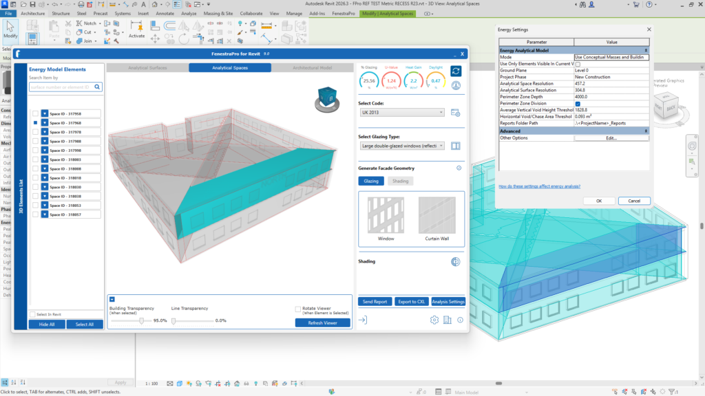
Summary:
- Results in FenestraPro are produced for areas in the Perimeter Zones, the size and shape of these areas may change depending on settings in Revit.
- Whether the model is open plan or has internal divisions will affect the perimeter zone areas generated (open plan layouts also may take longer to generate an energy model).
- Review Revit’s Energy Settings for Perimeter Zone Depth and Perimeter Zone Division to adjust the configuration if required.

