Model Preparation
The minimum required for a model to load into the application is that a successful Energy Model generates in Revit.
There is detailed guidance below but initially if an Energy model does not generate for a detailed model, you may check:
- Are the Energy Settings correct in Revit? (energy mode should be ‘Use Conceptual Masses and Building Elements’, the Ground Plane should be set correctly, is the correct Phase used? etc)
- Close any gaps in the building enclosure (try to place rooms on plan to see if spaces are enclosed)
- Check if incorrect elements are being used on the exterior envelope (eg. ceilings, generic objects, floors modeled as roofs, internal doors etc)
- Are element functions correct? (exterior walls must have ‘interior’ function etc)
- Are openings placed in the exterior walls before glazing is added? (remove these openings)
- Remove any room separation lines around the perimeter of the model
- Envelope elements and any linked files must be set as room bounding
- Are there any hidden elements in the model that may interfere with EAM (Energy Analytical Model) creation?
- Check warnings under Revit’s Manage tab
All Model Types
-
-
-
-
- Check that the Site Location is correctly set in Revit since this will affect Solar Data. This may be set in the Manage Tab – Location. This will affect results but will not stop the model loading.

- Model Orientation on site should be correctly positioned. You may need to rotate True North in Revit to achieve this. This may be done in the Manage Tab – Rotate True North. (Please do not rotate the model in a Revit View as this will not achieve the same outcome). It is possible to tell if the True North has been rotated by checking if the View Cube in Revit lines up with the compass circle (Front will normally line up with South if the True North has not been modified).

- Check that your Levels are correctly set and that they align correctly with building elements.

- Ensure that the Building Type is correctly set in the Energy Settings. This will define the occupancy hours. Alternatively, this may be adjusted in FenestraPro’s Building Manager.

- Optional but recommended: Create an Energy Model in Revit and check for relevant warnings in the Manage Tab – Warnings. Launching FenestraPro will automatically generate an Energy Model in Revit and display a message if this was not successful. Note: if the project has open plan areas it may take longer for the Energy Model to generate. It is recommended to place internal walls in Detailed projects so that the model conditions are as realistic as possible.


- Check that the Phase in the Energy Settings matches the one set for the elements that you wish to analyze (Existing/New Construction/Phase 1/2 etc). The Phase that is set in the Revit view should also allow display of relevant Conceptual elements if these are required. It is recommended to use the default 3D View in Revit as your main view and to close all other views.

- Check the Perimeter Depth in the Energy Settings is correct (typically it is set to 15-20 feet or 6 meters). Note: If the Building Elements Mode is set in Energy Settings, you will not be able to set the Perimeter Depth. The correct mode to use with FenestraPro is ‘Use Conceptual Masses and Building Elements’ in order to edit the value. The minimum value accepted is 1.5 meters (4.9 feet) and the maximum is 8 meters (26.24 feet). If values are input outside these ranges (larger or lower), the application will use a default value of 6 meters (19.68 feet).
 8. Use Mass objects for Surrounding Objects/Neighboring Buildings for both Detailed and Conceptual models. These can also be included to calculate Shading Effects.
 Conceptual Mass Models
- Assign Mass Floors in Revit by selecting the Mass and using the Mass Floor Tool on the Revit Menu.

- You may set Target Percentage Glazing in Revit’s Energy Settings or control this later in FenestraPro.

- The Mass should physically touch the Ground Plane Level that is defined in the Energy Settings. Adjust if required.

- The Mass should be created as recommended (create the model level by level). This may be done by modeling level by level while in the Mass Editor. When you click on ‘Finish’, this will be one mass but surfaces created in FenestraPro will be adjustable on each level. Extruding a mass from a footprint to the roof level will limit your ability to control separate zones.

- Avoid core extrusions (either solid or void) within the Mass (elevator/core shafts etc). To model voids inside a Mass, the footprint is best separated into pieces as required (the Mass remains as one when complete). Voids and extrusions which overlap however should be avoided as these tend to interfere with the identification of analytical energy surfaces. Void extrusions will not appear as issues under the warnings area in Revit however.

- When extruding planes in Mass models, some areas may go out of alignment or out of axis which can cause issues when attempting to create an energy model. If you suspect that this is the case, review the model and revise if possible. It may be necessary to redo parts of the model again where areas do not join correctly or planes do not align. There should be no gaps or overlaps between floor planes on each storey.

- If the Perimeter Depth setting is turned on/off in Revit, it can affect the number of analytical Surfaces generated on a Conceptual model depending on the shape/massing of the project. This is because with an open plan arrangement, the divisions are displayed on the model. Where these intersect with the outer envelope, Surfaces are created. If this is not desired, turn off the Perimeter Zone Division setting (under the Energy Settings in Revit) so that it does not display on the model.
 Detailed Models
- Check that Thermal Properties are set for element types/families in Revit. Analytical Properties (R-Values and U-Values) will need to be assigned to model elements. This may be checked by selecting elements and using Type Properties/Edit Type to check if these are assigned.

- Avoid large gaps in the building enclosure. This will interfere with the creation of a successful energy model which is required for analysis. This is true for Walls joining Floors and Roofs as well as other adjacent Walls and missing soffits under Roof Overhangs etc.

- Check that ‘Areas and Volumes’ is set under ‘Rooms and Areas’ in Revit, instead of ‘Areas only’.

- Element Functions should be correctly set. Exterior walls and Floors should have an ‘Exterior’ function. Internal Walls (solid and curtain walls) should have an ‘Interior’ function. Elements with Interior functions will be excluded in the results. Note: The Energy Model in Revit may identify this as an external element despite the Revit function setting. The Revit setting however will be used by FenestraPro and the element will be excluded.

- Avoid overlapping elements (floors/walls etc) or multiple instances of elements in the same position. Revit may list these in warnings under the Manage tab which may be reviewed and model conditions can be improved.

- Ensure that relevant elements are Room Bounding. Linked models should also be Room Bounding (this may be set in the Host model).

- Rooms may or may not be placed (this is not required as the application will not rely on this data). If placed, Rooms/Spaces should be placed correctly and upper limits extend to the next level. Creating a Room Schedule is helpful for identifying redundant rooms, rooms outside the model etc.

- Check Room Computation Heights are correct for measuring the room perimeter. This is the plane at which the room area is calculated. In some cases, this value may be set above the floor level and may cause issues if walls are sloping etc.

- Avoid Room separation lines around the model perimeter (inside the envelope) which interfere with Energy Analysis. The model elements (walls etc) should define the bounding conditions instead of room separation lines. If these are present, these terminate the internal spaces instead, leaving the envelope surfaces incorrectly excluded from the Energy Model.

- Note that Stacked Walls may not read correctly. This is because properties cannot be assigned to these wall types in Revit.

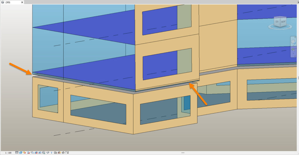
- Avoid modeling separate layers of walls adjacent to each other (walls beside other walls) with glazing hosted on the inner wall. Wall assemblies may be managed using Type Properties -Structure, where you can define layers, thicknesses and materials.
 12. Review warnings in Revit under the Manage Tab. This will list any issues in the model which prevent a successful Energy Model. Not all issues may be listed here however and some may not be critical for Energy Analysis (stair risers/treads etc).
- Assign Mass Floors in Revit by selecting the Mass and using the Mass Floor Tool on the Revit Menu.
- Check that the Site Location is correctly set in Revit since this will affect Solar Data. This may be set in the Manage Tab – Location. This will affect results but will not stop the model loading.
- 13. Check that internal walls do not extend into the core area of external walls (this may interfere with identification of elements and energy analysis).
14. It is recommended to use only the default 3D View in Revit and Close any other Revit views if they are open in the background (elevations, sections, plans etc).
- 15. Structural Columns that are set to room-bounding may cause issues (high results) if they are touching, very close to glazed elements or embedded in walls. A workaround for these is to temporarily set them to non room-bounding.
 16. Curtain Panels must be modeled as panel families in Revit (not wall families) to allow analysis. Wall families cannot be assigned Glass Types under Type Properties (Analytical Properties) or by using the Glass Database in FenestraPro.17. Avoid placing openings in exterior walls and then inserting glazed elements into these voids. This typically interferes with the Energy Model in Revit and the glazed elements may not be identified. These areas may not then receive analytical surfaces and will be excluded.
- 18. If Energy Surfaces are fragmented and appear to be missing some areas, you may adjust the analytical resolutions under Revit’s Energy Settings to get a more accurate surface. Under the Analyze tab on the Revit menu, find the Energy Settings and adjust the Analytical Resolutions. Note: the Energy Model may take longer to create depending on resolution settings and results in the application may vary as resolutions are adjusted in Revit (as surface areas will typically change).

- For more details of each item, Please refer to Sections 12.1.1, 12.1.2 and 12.1.3 below.
- Click here for a video on Best Practices for using Detailed Revit models with FenestraPro:

-
-


-
-


 8. Use Mass objects for Surrounding Objects/Neighboring Buildings for both Detailed and Conceptual models. These can also be included to calculate Shading Effects.
 Conceptual Mass Models


 12. Review warnings in Revit under the Manage Tab. This will list any issues in the model which prevent a successful Energy Model. Not all issues may be listed here however and some may not be critical for Energy Analysis (stair risers/treads etc).


 16. Curtain Panels must be modeled as panel families in Revit (not wall families) to allow analysis. Wall families cannot be assigned Glass Types under Type Properties (Analytical Properties) or by using the Glass Database in FenestraPro.
 17. Avoid placing openings in exterior walls and then inserting glazed elements into these voids. This typically interferes with the Energy Model in Revit and the glazed elements may not be identified. These areas may not then receive analytical surfaces and will be excluded.