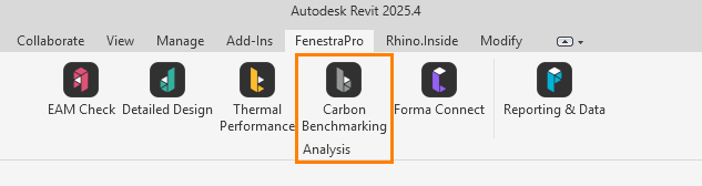
The Carbon Design Tool can be found on the Revit menu under the FenestraPro section. This will allow you to produce a Report on Operational and Embodied Carbon values for your project.
Initial Preparation:
IMPORTANT: Since this is a beta preview, once you install FenestraPro, please use the Detailed Tool first to enter your serial key if required and login. This can then be closed and you may launch the Carbon Analysis Tool. The Carbon Analysis feature can currently be used in both Revit 2023 and Revit 2024.
To avoid having to do additional modeling, you may use Revit sample models which may be found in this location: C:\Program Files\Autodesk\Revit Version\Samples
Note: A systems Analysis report will need to be created in Revit. This may be prevented in Revit sample model folders due to restricted user permissions set for that folder. To resolve this, you may change the default report location in Revit’s Energy Settings – ‘Reports Folder Path’.
If using your own model, ensure that the Energy Settings requirements are first defined (as described below) and that the model is saved (the model must first have a name so that the report can be saved to the same folder). A Systems Analysis report will not be created if a template file is open and a model linked in without saving the project. The model may be a linked file as long as it is set as room bounding and an Energy Model is created in the host model. Rooms placed in the linked model will be read in Revit to create the Systems Analysis report (rooms do not have to be recreated in the host model). The Systems Analysis Report may take time to generate depending on the model complexity since extensive data is extracted, please be patient and allow this to complete.
You may also use our detailed workflow models on this website here.
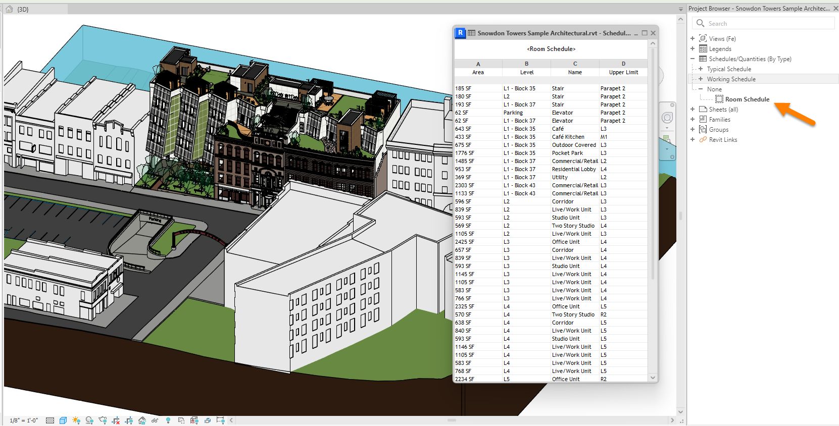
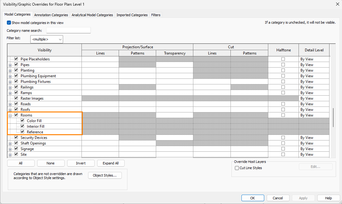
1. Rooms need to be added to each Plan View for the model to include all important spaces. Any non-placed rooms or rooms on roof terraces must first be removed from the project. You may check if all rooms exist by reviewing an existing Room Schedule in Revit creating a new one if required. Any entries with zero areas or tagged as ‘not placed‘ should be deleted. You can also view Rooms on each Floor Plan by going to Visibility/Graphics in Revit and checking the Rooms checkbox and turning on 1. Color Fill 2. Interior Fill and 3. Reference. Note: You will only see these Room settings when a Plan View or Section View is opened in Revit. You may also first need to adjust the View Template settings in Revit before you modify the view settings.
3. It is assumed that glazing elements in the model have been assigned glass types in Revit’s Type Properties or using the FenestraPro Detailed Tool (simply launch this application and use the Assign Glass button to check for missing glass properties). Other element properties in the model are defined by Schematic Types in the Advanced Energy Settings (see below).
4. Under the Energy Settings in Revit, go to the Advanced tab – Other Options (1). Under Material Thermal Properties – Schematic Types (2) click on the 3 dots to the right of this field to open the settings.
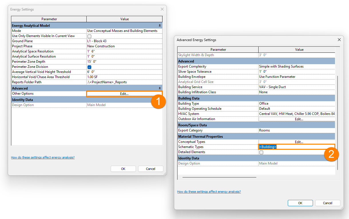
5. In the settings window (3), check the boxes for all element types except Exterior Windows – this will mean that Schematic Types (defined here in the dropdown lists) for these building elements will be used here. You may use the dropdown lists to define specific analytic constructions for Roofs, Floors, Exterior Walls etc). For Exterior Windows, we wish to use properties displayed under Type Properties for the glazing elements. There is a detailed explanation about this from Autodesk here.
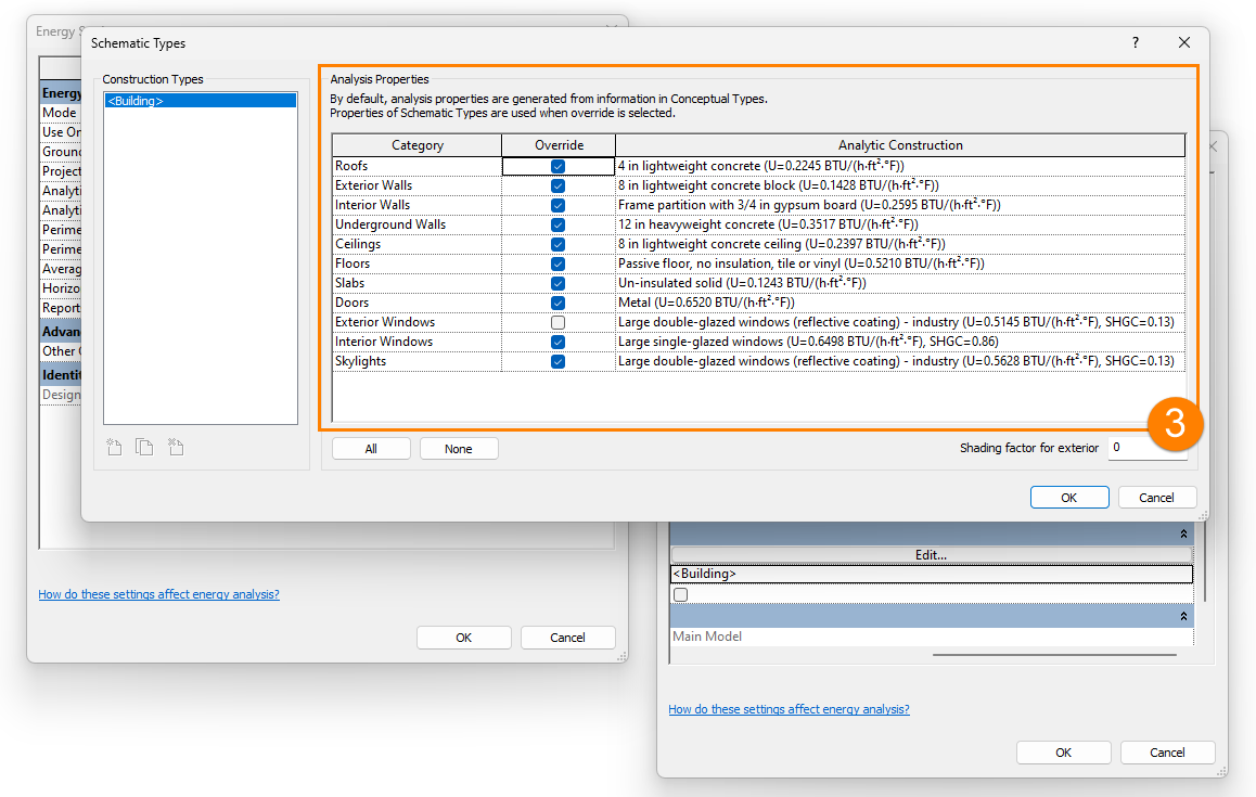
6. Check the Detailed Elements checkbox if it is not already checked. This will ensure that materials based properties in the model will be used

7. Delete any previous Energy Models if they were created previously in Revit (Analyze tab – Energy Optimization panel).

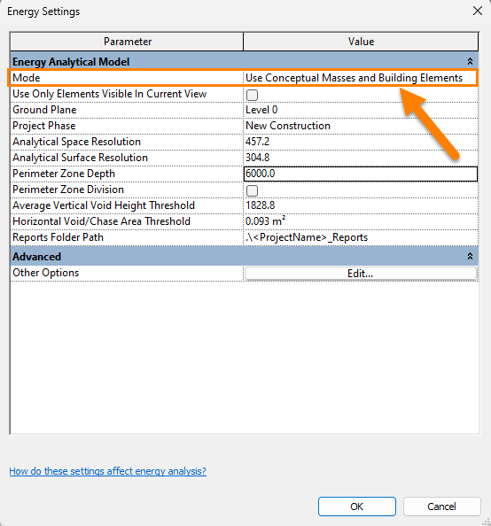
8. Go to the Energy Settings on the Revit menu (Analyze – Energy Settings) and ensure that the mode is set to ‘Use Conceptual Masses and Building Elements‘. Create a new Energy Model (Analyze – Energy Settings). Note: The Areas and Volumes setting should be defined in Revit under the Architecture tab – ‘Room and Area – Area and Volume Computations’.
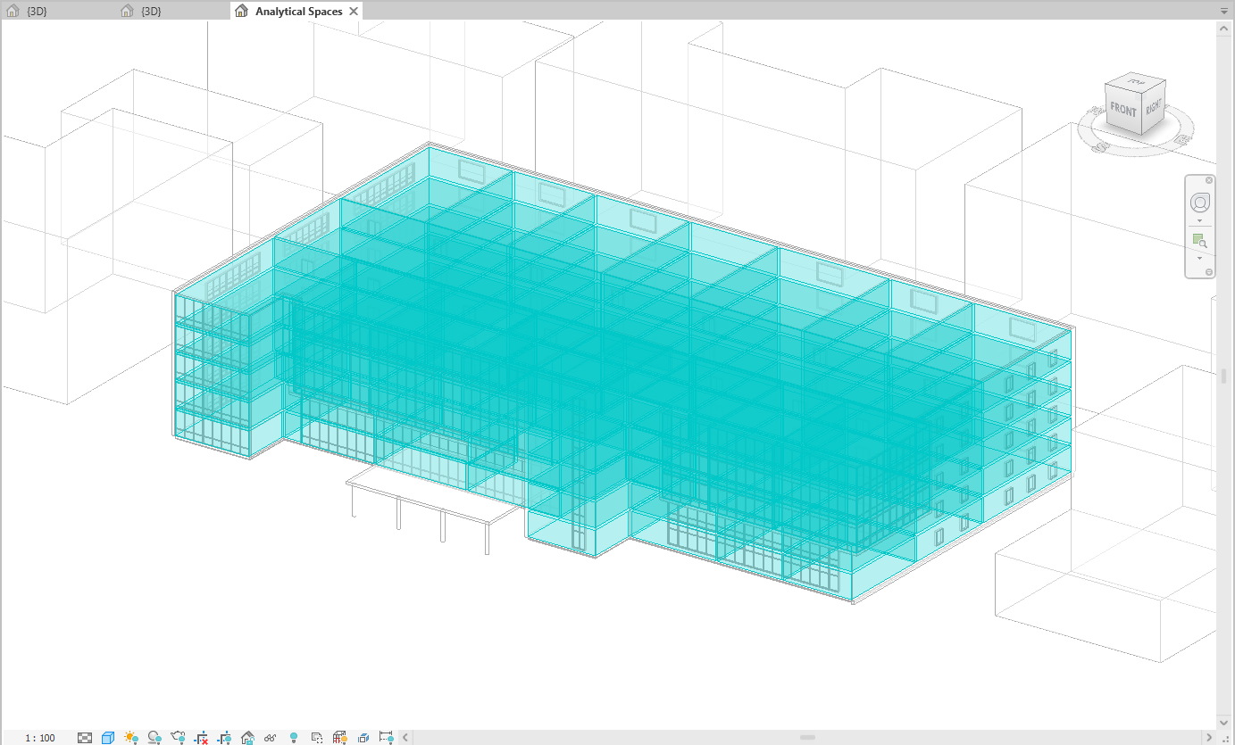
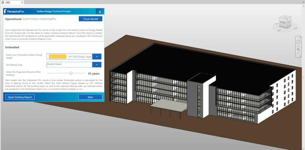
9. Once the Energy Model has generated, you may open the Analytical Spaces view in Revit to check if all Energy Spaces are present. You may stay in this view or switch to a default 3D Revit View. Note: a 3D View must be explicitly opened and active to use the Carbon Tool. If a message displays to use a 3D View, please go to View on the Revit menu and select the 3D View.
10. From the Carbon Analysis application, use the Check Model button to verify if settings are correct to proceed. If not, a panel will display with guidelines. If the model condition is suitable, an ‘Energy Model Ready‘ message will display.
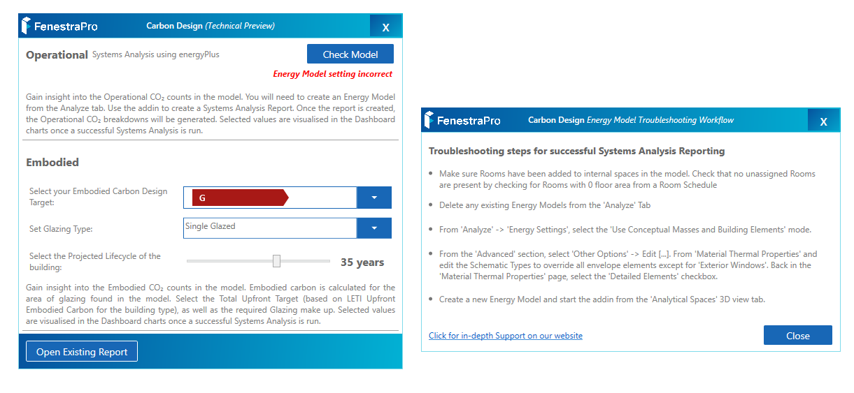
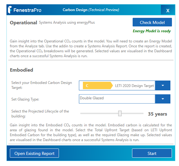
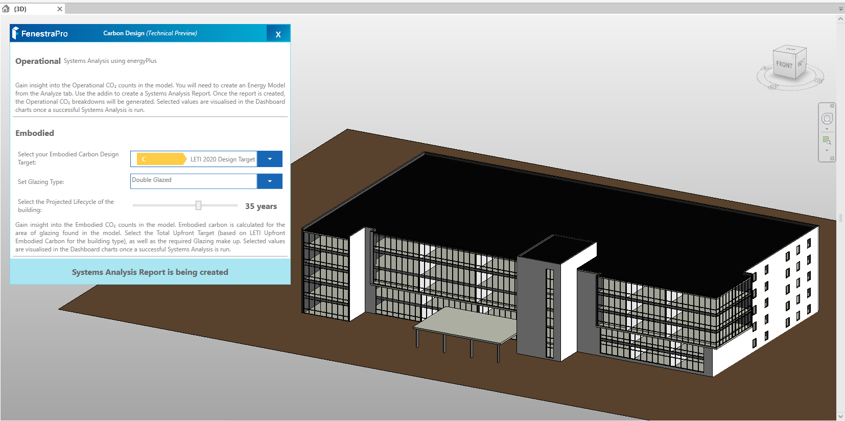
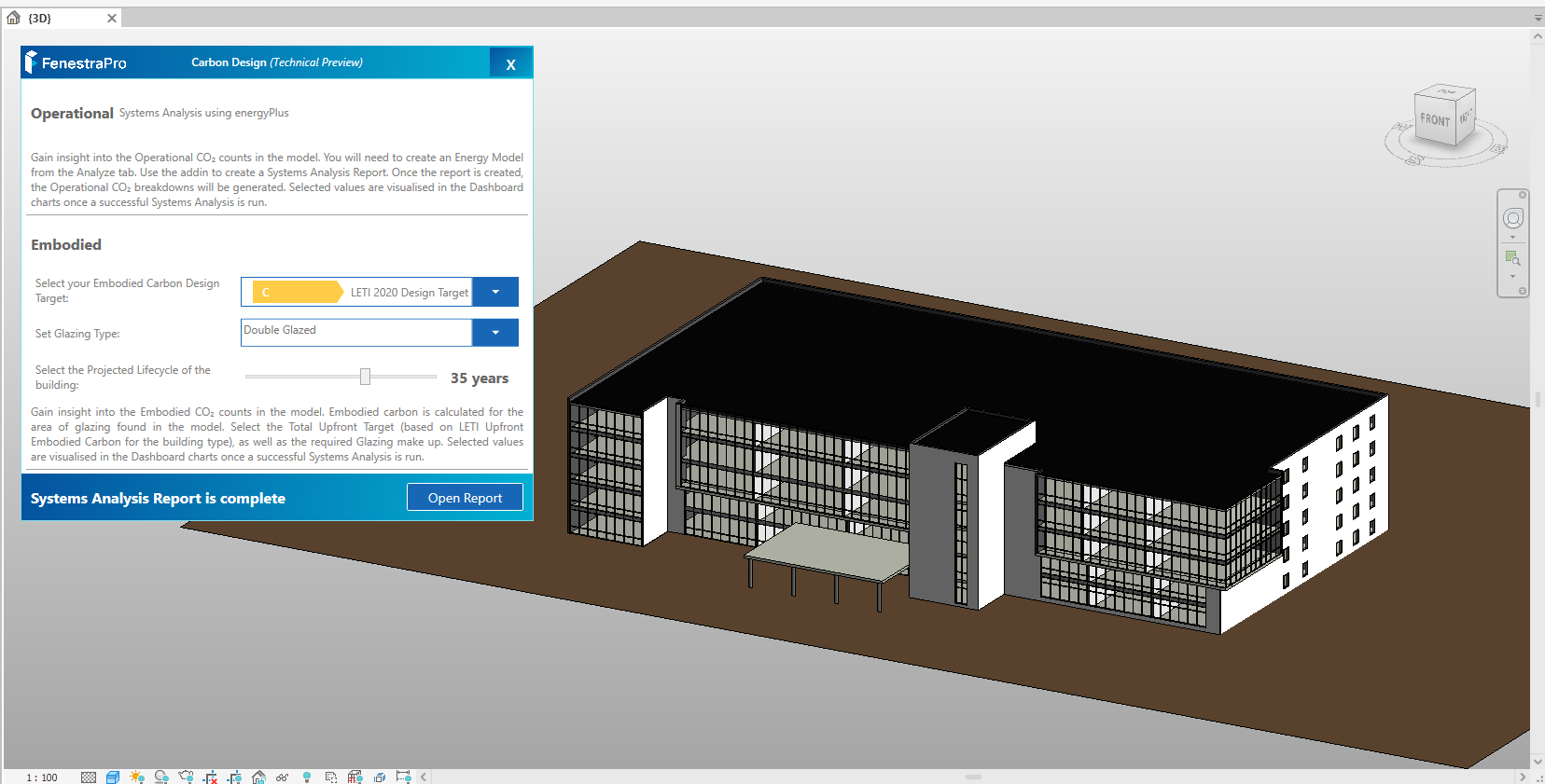
11. There are 3 settings to define: 1. Embodied Design Target Band 2. Glazing Type and 3. Projected Lifecycle. Then click on the Start button. This will create a Systems Analysis report using energyPlus in Revit. The application will use this data when presenting carbon information. Allow the report to complete in the background (at the bottom of the Revit screen, a dotted circle will spin until the report is complete). Note: If you are analyzing one of Revit’s sample models, you may not have permission to create a report in the default project folder. In this case, you can change the folder path to a different location on your computer (using the Energy Settings in Revit). If you have issues creating a Systems Analysis Report in Revit, there is also help from Autodesk to troubleshoot this here
When the report is being created, a message will display to advise.
If the Systems Analysis Report was previously created, then deleted or moved, a red X will display in the Project Browser. You may then create a new report using the Start button in the FenestraPro Carbon Tool, or click on the X to get guidelines from Revit.
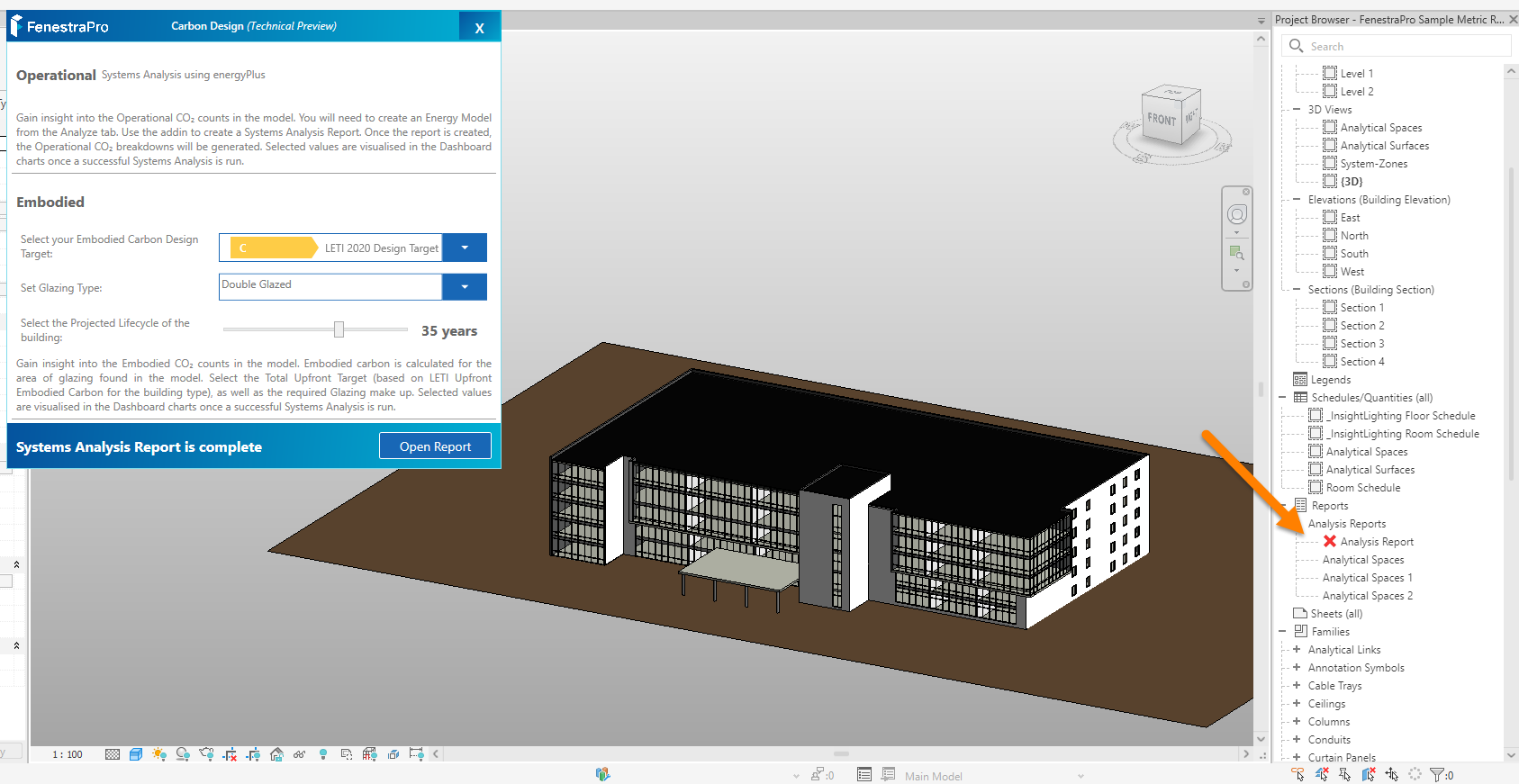
13. Once the report has completed, a message will display and a button will appear to Open Report. Note: larger and more complex models will take longer for the report to process.
If you reopen the Carbon Analysis Tool in subsequent session and you have previously created a report and saved the model, there will be an option to open an existing report.
Workflow Summary:
- Ensure that rooms have been added to the Revit model (with no zero area rooms or non-placed rooms left over)
- Ensure that glass types are assigned to all glazing families in Revit (using Type Properties in Revit)
- Check the Advanced Energy Settings in Revit are correct (Energy Mode is correct, ‘Detailed Elements’ checkbox is on, Schematic Types are checked except Exterior Windows)
- Check that the Areas and Volumes setting is checked in Revit
- The Revit model is saved in some location with a project name
- Create an Energy Model in Revit
- Launch the application and click the Check Model button (adjust settings in Revit if message advises). If Energy Model Ready displays, proceed.
- Define target values (Upfront Target and Glazing Type)
- Click Start to generate the report
- Open the Report to view the outputs
Detailed Workflow for the Carbon Tool
- Click on the FenestraPro Carbon Analysis Tool on the Revit menu (a new window will open).
- Click on the Check Model button. A window will open to provide guidance on what is required to analyze the model and if there are any issues before you proceed e.g. if the energy model mode is incorrect etc. There is also a link to guidance on Energy Model issues on our Support Site.
- If you had to make any changes to the Energy Settings, create a new Energy Model in Revit (from the Analyze tab – Energy Optimization area.
- In the Carbon Design Tool window, define settings for Embodied Carbon Design Target and Glazing Type.
- Click on the Start button to generate a Carbon Report. Revit will display a message on screen when the Report is ready. If an existing report exists, you may open this to review the results. Note: It is not advisable to adjust the Energy Settings in Revit or make modifications to the model while the report is being created.
- A new window will display with the results. You may go back to the previous window by using the Back arrow on the top right corner.
- You may adjust the target values and use the Open Existing Report to get new results using the new settings (you do not have to generate a new report).
- The Results will display Total Operational Carbon, Total Embodied Carbon, Embodied vs Operational Carbon breakdown, Envelope vs Non-Envelope Operational Carbon, Embodied Carbon for Glazing and overall Window to Wall ratio.

![]()
